Your cart is currently empty!
Self-Pierce Riveting explained
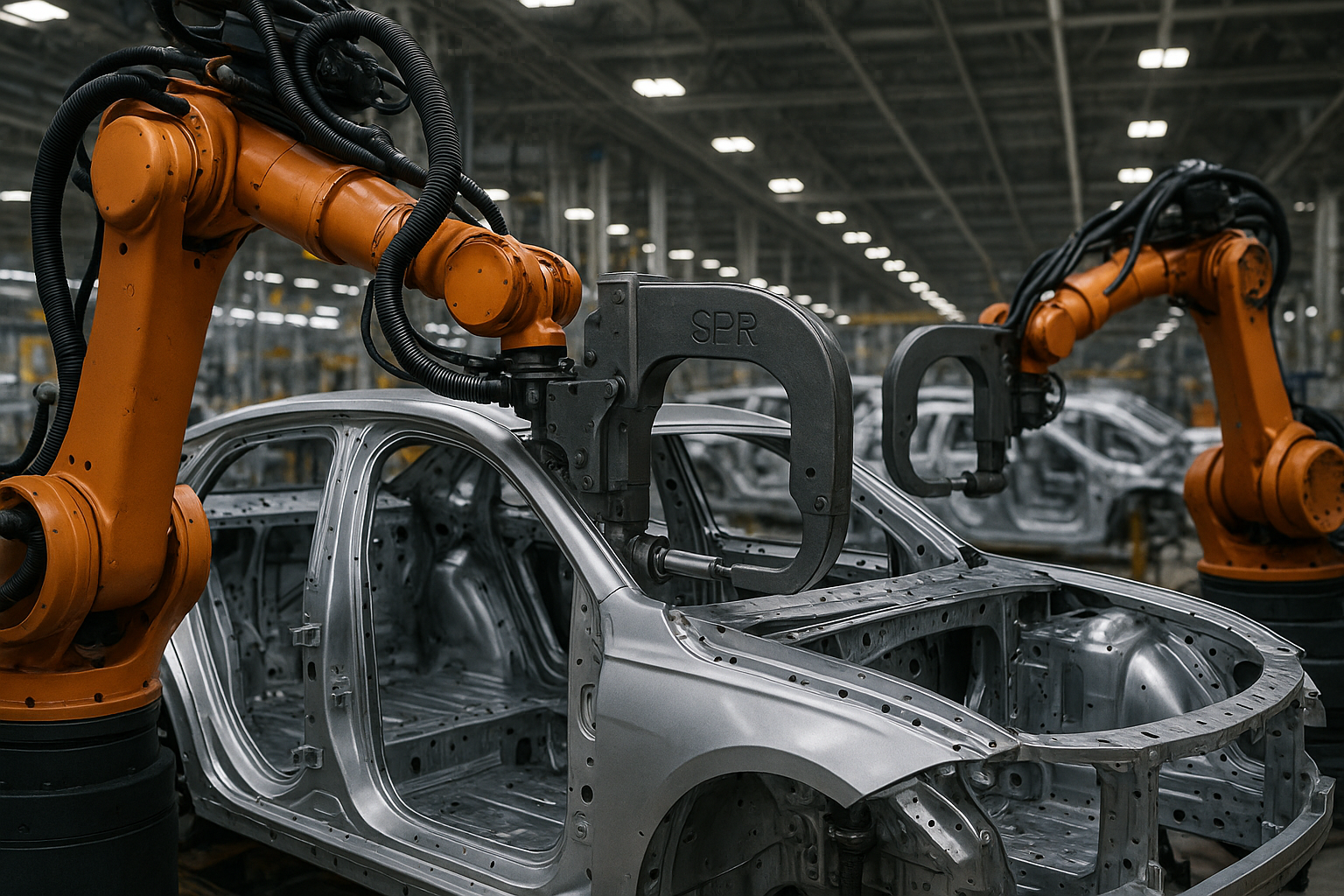
What Is Self-Pierce Riveting (SPR)?
Self-Pierce Riveting (SPR) is a mechanical fastening technique for joining two or more layers of material without a pre-drilled hole. A semi-tubular rivet is driven through the upper layers, flaring out within the bottom layer to create a mechanical interlock — crucially without breaking through the bottom surface.

It is a cold joining process widely used where materials are difficult to weld, such as in automotive aluminium structures.
The SPR Process Steps
- Clamping: Sheets are tightly clamped between a die and blank holder.
- Piercing: The rivet is driven at high force, penetrating the upper sheets.
- Flaring: The rivet shank flares inside the bottom sheet, creating an interlock.
- Release: The punch is retracted, leaving a strong, permanent joint.
The bottom sheet remains intact, making SPR ideal for structural integrity and sealing.
New Developments in Servo-Driven SPR Systems
Traditionally, SPR systems were hydraulic — applying steady force — or inertia-driven, using a spinning flywheel to deliver a high-energy impact. Recent advances introduced servo SPR systems, offering:
- Permanent Magnet Synchronous Motor driving the rivet via:
- Belt drive.
- Planetary Roller Screw Mechanism (PRSM).
- Integrated Clamping Mechanism and C-Frame.
Servo systems allow precise control over:
- Setting velocity.
- Motor current limit.
- Stroke offset.
This results in finer control of joint quality and energy efficiency.
System Dynamics and Modelling Insights
A physics-based model has been developed combining analytical and empirical approaches:
- Full system dynamics model (motor, belt, roller screw, clamp, C-frame).
- Joint force-displacement relationships derived from experimental data.
The model predicts:
- Head height.
- Cycle time.
- Energy consumption.
Validation against experimental data shows less than 5% error in force prediction and head height within ±0.25 mm.
Materials Suitable for SPR
- Aluminium alloys (e.g., 5754, 6000 series).
- High-Strength Steels (HSS).
- Magnesium alloys.
- Dissimilar materials (e.g., aluminium to steel).
- Composite materials (with adapted rivet designs).
Advantages of SPR
| Advantage | Details |
|---|---|
| No Pre-Hole | Rivet pierces materials directly. |
| Cold Process | No thermal distortion or heat-affected zone. |
| Dissimilar Materials | Suitable for aluminium-steel joining. |
| One-Side Access | Only the punch side needs access; die is positioned underneath. |
| Automation Friendly | Highly adaptable to robotic assembly lines. |
| Environmentally Friendly | No fumes or sparks, minimal energy use (particularly with servo systems). |
| Fatigue Resistant | Excellent fatigue performance, enhanced with hybrid adhesives. |
Limitations of SPR
| Limitation | Details |
| Material Ductility Required | Brittle materials may crack during insertion. |
| Die Access Needed | Die must be positioned under sheets — limits some applications. |
| Thickness Limitations | Optimal for total stack thickness of 1–10 mm. |
| Rivet Corrosion Risk | Requires coatings or careful material choice to prevent galvanic corrosion. |
Process Parameters Impact
The SPR process is sensitive to:
- Setting velocity: Higher velocities reduce cycle times but affect energy consumption.
- Motor current limit: Balances force application and system wear.
- C-frame stiffness: Influences force absorption and joint quality.
- Stroke offset: Shorter offsets improve cycle time and reduce energy use.
Key Equations in SPR
Rivet Force (Static Model)

Where:
is the force exerted by the rivet punch.
is the rivet insertion displacement.
Polynomial Fit Example:

Material Stack Compression Force

Where:
is the effective stiffness of the material stack.
Energy Consideration

The work done is the energy absorbed by deformation and friction.
Motor Dynamics

Where:
is the motor inertia.
is the electromagnetic torque.
is the pulley radius.
PRSM Force

C-Frame Deflection

Where:
,
, and
are mass, damping, and stiffness of the C-frame.
Head Height Prediction

Where:
is the initial punch-clamp offset.
Energy Consumption

Where:
is DC bus voltage.
is DC bus current.
Comparison to Other Joining Methods
| Method | Heat Input | Pre-hole | Dissimilar Materials | Automation |
| SPR | No | No | Excellent | Excellent |
| Resistance Spot Weld | Yes | No | Poor (Al–Fe) | Good |
| Mechanical Fastening | No | Yes | Good | Moderate |
| Adhesive Bonding | No (cure heat) | No | Excellent | Moderate |
| Friction Stir Welding | Solid-state | No | Good | Moderate |
Applications of SPR
- Automotive: Body-in-White (BiW) structures, EV battery enclosures, doors, and hoods.
- Aerospace: Lightweight structural panels.
- White Goods: Appliance structures where dissimilar metals are used.
- Electronics: Precision casings and lightweight frames.
Future Trends in SPR
- Hybrid SPR + Adhesive Systems: Combining mechanical fastening with adhesive bonding.
- SPR in Composites: Modified rivets and process parameters for fibre-reinforced polymers.
- Die-less SPR: Eliminating the need for die access.
- Smart SPR Systems: Integrating AI and machine learning for process monitoring and control.
Conclusion
Self-Pierce Riveting is a critical technology for modern lightweight and multi-material structures. Innovations like servo-driven SPR systems enable precise, efficient, and sustainable joining, with significant productivity and energy savings.

As industries move towards electric vehicles and sustainability goals, SPR — particularly with advanced control systems — will become even more indispensable.
Advanced Joining Methods, Aluminium Car Body Joining, BiW Assembly Techniques, Body-in-White Riveting, Cross-Sectional SPR Joints, Electric Vehicle Assembly, Lightweight Joining Methods, Self-Pierce Riveting, Servo-Driven SPR Systems, SPR for Aluminium Sheets, SPR in Aerospace Industry, SPR in Automotive, SPR Joint Design, SPR vs Spot Welding, Structural Riveting Technology